Job Done, Finally!
(This is a post in my series about my Garage Door Opener. Yes I wrote a series. About a Garage Door Opener. Check it out:
Okay, so I've written a little about this before. Back in 2013 I added a light to my garage door, and then started to work out how to control it with my phone.
Let me (finally) tell you how I did it!
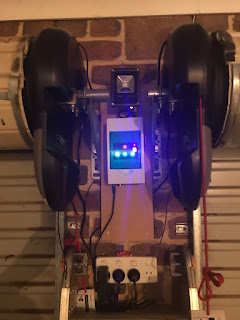
Installed and Ready to Go!
Design the First:
After grabbing some EDP-01 modules from eBay, I thought the way forward would be to simply use the two free GPIO's to drive relays salved across my roller door control buttons.
But, this approach rapidly ran into a few issues:
- Of the 8 pins available, 2 are power, one is Reset, one is CHPD which is connected to VCC
- Tx and Rx are required for programming - so it's awkward to build those into a design.
- That leaves GPIO_0 and GPIO2 where:
- GPIO_) has to be held low when resettting the module to put it into programming mode and
- GPIO_2 seems to randomly toggle when the module powers up
So, all that combined means that if I was to control relays with the ESP-01 module directly, each time it rebooted it would fire the relays and open the garage door. For example, a black out in my neighborhood could open the door for all and sundry. Not an option.
My solution? Pair it with a microcontroller and send serial commands from the ESP-01 to the micro, and then have the micro control the relays. Simple!
Like this:
I designed it to fit the following case, as it would allow me to easily mount the unit on some DIN rail, for a neat installation.
And the prototype was built, and pretty much worked.
But there were a few issues, as always.
Programming it was a pain in the butt. I had to pull the ESP module to upload code and there was no way to trigger it locally (no button to push!).
It *did* give me a platform to cut my teeth on HTML / CSS and Javascript, but I was soon onto Version 2.
So the requirements for the new opener became:
- Buttons, so it's easy to operate
- Have a button to control a light, like the old opener
- Use a better, 12V DC light rather than wedging in a mains voltage bulb
So I came up with this!
Much Betterer!
To do this I moved up to the next case size (from Aliexpress):
And mounted it inside this enclosure.
Here is where I trial fitted the second prototype. The blue LEDS on the bottom were controlled by the relays that were to slave across the roller door buttons, with the yellow one simulating the to-be-installed light.
The screw terminals on the top are for the power connection *and* remote inputs for each door (I went with three, because even thought I only have two doors, some friends have three) and the light. This is because my home alarm has remote controls that I use to open / close the roller doors. My post on the light installation explains this in detail.
Beauty shot with blinkenlights.
Better Fitment shot.
Final Installation with eBay '12W' LED Lamp
Version 2 - The Misses
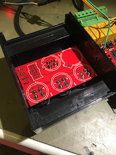
Version 2 came together pretty quickly, and to avoid messy internal wiring, I decided to mount the Buttons and Indicator LEDS on a separate board in the case.
Like this mess inside my old controller....
The Buttons themselves are panel mount, so it's a case of install buttons in the lid of the case, and solder the carrier board to them.
Like this:
Here I'm showing the LED riser board I also used on the carrier board. My first attempt didn't use this riser, but instead I tried Light Pipes. However these were tricky to align and I wasn't that successful at blocking light from one LED bleeding into another light pipe. And in 'wasn't successful' I mean 'I never tried'.
Not to get this image above I had to make the LED riser board as a step model. However I couldn't work out how to do this in Circuit Maker, so I laid it out again in Altium and exported it to a step model there. That said, I'll link to all my Circuit Maker files at the end.
To ensure alignment, I also designed a drilling template in Circuit Maker:
Of course I can't find it now... I milled this at work and it snapped nicely into the top of the case.
I drilled 1.5mm location holes with the jig, and then opened up all holes to 3mm (to suit the LEDs) and then finished the LED holes with a step drill.
Then, with the case hole drilled, I also had a nice jig for locating the LEDs in the riser board - like this!
My soldering here was a touch unorthodox - I soldered the joints from the top and then sodlered the joints on the other side afterwards.
Once the riser was ready, I assembled that on the carrier board:
Then I fitted the CR2032 battery holder and the header for the ribbon cable to connect it to the motherboard. I then loaded the carrier board into the lid, soldering the button pins in place to secure it.
This picture above shows the first board revision where the LEDs were to be fitted to the carrier board. Also you'll note that the IDC header is only 12 pins where the following version used 14. Why? Initially I'd tried multiplexing the LEDs but the ESP-12 was too busy processing webpages etc and the multiplexed LEDs would noticeably flicker. Adding extra lines to drive the LEDs directly solved this issue.
Here you can see how mounting the LEDs directly on the carrier board (using the full length of the LED legs) had the LEDs falling short of the front of the case. The riser board fixed this issue.
Why the battery? I design in a Real Time Clock into my board, with the thought that I could later add higher level features such as 'Door Open Too Long' or inhibit the door working when no one should be at home (e.g. between 10AM and 2PM) but I soon gave up on this idea. Why possible, I since discovered MQTT and Node Red, so will look at implementing these features using those tools later.
As discussed, a Ribbon cable connects the carrier board to the main board. This is the first iteration and there's a few changes since this version:
- Like a newb, I'd surrounded the ESP-12 module with a ground plane. So I peeled it back except for the serial lines that lead to the programmer.
- You'll see there's three tact switches on the board:
- Two are used to put the board into programming mode. Trust me, this is a pain in the butt that gets old fast.
- The idea for the third was that if held down when power cycled, it was to boot as an access point so you could configure the WiFi settings. I also abandoned this idea!
My second iteration moved the ESP-12 module closer to the front of the board, and had the ground pour aoid it correctly, but still used two tact switches to set the programming mode. I'd dropped the 'force access point mode' button as I'd written the software to start as an access point if it cannot connect to the configured WiFi making this mode redundant. Also, it's this version where I'd realised the issues with multiplexing my LEDs.
Here you'll notice that there are no longer any tact switches on the board. I've broken out the GPIO_0 and Reset lines out on the 5 pin header (along with Ground, Tx and Rx data) and now use an external programmer. This emulates the Ai-Thinker reference design:
In this board:
And I'll spill all the details about that in another post.
And here's the latest version board with latest version carrier board.
For this iteration I used Yellow and Blue buttons, but fell back to Red and Green for the final installation. I may swap back to the Yellow / Blue later.
Aware that this post is getting a little long, I'll go into a more detailed explanation of the schematics / software in another post. But for now I'll focus on the actual install.
Putting it on the Wall
First, the old light and switch box had to come out:
And was unceremoniously dumped on the ground.
I used a small MDF board to mount the last controller, and thought I'd do the same again, but also incorporate the eBay LED lamp.
A quick trial fit of the layout was sorted.
Also - note the Raspberry Pi case - I will install this as my Node Red / MQTT server 'soon'.
Installed, wired up.
And then I was ready to test.
Disaster!
Ok, this is where I admit I'm a dumbarse. When I laid out my PCB I thought I'd make it dual use. A change of software, and I could re purpose this as a garden watering controller. To do that, I'd included solder blob links to either configure the relays to be 'dry contacts' or switch 12V.In this mode, I did all my testing with LEDs attached. Press the button, on the opener or on the webpage and the LEDs would blink.
Great. Except I forgot all about this. I pulled the LEDs, and wired the realys to my roller doors.
Here, the plot thickens a but further. Most roller doors have in input for an external button. Mine didn't. Note, post tense.....
Anyway, to get my old light controller working, I cracked open my roller door motors, and soldered some flying wires across the built in 'open' button. Like this.
Worked fine, literally, for years.
Until I tested my new opener. As this is an internal button, there's pretty much a direct run at the microcontroller from this contact. A PIC micro actually. With no over voltage protection on the pin.
So, one button press later, 12V was switched straight into the micro, and the input pin was forever buggered. So, out with the now ruined roller door motors....
And in with a new pair from Bunnings.
And yes, these new ones have lights. Darn it.
Anyway, I continued with the install, using the 'Remote Input' on the new motors and, soon, Job Done!
Finally, I can open my garage doors, using my phone.
Next time the kids have an idea, I might think about it a while before committing to it!


This comment has been removed by a blog administrator.
ReplyDeletePython raise keyword
ReplyDeletenumpy dot product
Floor function in PHP
Convert array to list Python
Convert list to dictionary Python
Count consonants in a string Python
Count vowels in a string python
Python program to add two numbers
Python program to find area of circle
Wow, what an adventure with your garage door opener! Your dedication to improving and customizing the system is impressive. It's fascinating to see the evolution from design challenges to the final installation. But, If anyone requires expert assistance in garage door installations or upgrades, CR Garage Doors could be the perfect solution for quality and professional service. Also, cheers to your persistence and innovation
ReplyDeleteThank you for sharing this blog. Your detailed explanation and step-by-step process make it seem achievable, even for someone with limited technical expertise. Your dedication to improving and automating your garage door opener is truly commendable.
ReplyDeleteInsulated garage doors are specifically designed to improve energy efficiency by reducing heat loss from garages. Constructed with advanced insulation materials, these doors help maintain a consistent temperature, protecting stored items and contributing to lower energy bills. Insulated garage doors also enhance soundproofing and durability, making them an ideal choice for both homes and businesses.
ReplyDelete