Home Alarm Monitoring
I have a home alarm system, and it's reliable and the monitoring company provides a good service. For a bit less that a dollar a day, if the alarm goes off, they give me a call.
Each and every time it goes off.
My system has multiple zones, and my thinking is that if only the one zone is triggered, it's probably not a burglar in the house. And I don't want my long weekend away spoiled by my wife continuously worrying about the single zone alarm that went off 2 hours ago and we are not going to be home for two more days.
I've requested with the monitoring company to *not* call me when it's only one zone, but policy is policy and they need to call. Fair enough.
Inspiration and Requirements
For a long time I was 'going to do something' about this. I've a stack of old Nokia Mobile phones lying around and was thinking of interfacing to the alarm, decoding the DTMF, and then sending out a text via serial FBus / MBus commands to the mobile. I've always enjoyed interfacing with phone stuff.
Then I stumbled across Lior's Alarmino project. What really got my interest up was the SIM900 module he used. For about $20 you get a quad band GMS module that will result in a much more presentable product than a hacked mobile phone. I've used a gyrator circuit before on a telephone line multiplexer for a building wide intercom, but I'd never tweaked that you can use a gyrator to simulate the line as well. Sweet.
And believe it or not, I've never used an Arduino in a design before. So this was a great idea to try and implement this. To make life easier (I can't be bothered with software uarts and the timing overheads this requires) I thought I'd go with a Leonardo clone. On board UART to talk to the SIM, on board USB to bootload over. Sweet.
Finally, as I want to get into home automation, this device could also act as an SMS gateway - I could send it a message, and relay this into some larger control system via USB. Sweet.
Even sweeter, my software engineer buddy also wants to cut out his third party alarm monitoring, and he's going to write it. We've also decided to share all the works as open source and thus the Nick and Simon Co-Operation, NASCO, was found. I kinda went nuts with the schematics and logos - you know the important stuff that gets in the way of actual work :)
Doing it My Way
I made a few mods to Lior's circuit to suit my needs. There's nothing wrong with how Lior implemented their design, it's just some preferences.
For the off hook detection, Lior sampled the voltage across a shunt resistor with his micro's A2D. I've gone with an old fashioned comparator circuit - imho it's easier to code for a change on a digital input rather than read an A2D. In support of Lior's idea, you could adjust the trigger point via firmware to suit the alarm panel you are using, but mine can be simply set via a trimpot.

I've also left some design notes on my schematic explaining how I derived my values for the Gyrator. Notice that I used an LED for a voltage reference for the comparator. I did this rather than use a simple voltage divider as the LED provides a fixed voltage that's independent of supply rail variations.
Normally I'd not go to the trouble, but in reading the SIM900 datasheet I found that it can sink 2A during transmission bursts, and I don't want the interface to false trigger due to supply rail sagging.
I also used an active filter to smooth the kiss off tones I'll be transmitting to my alarm panel, rather than the lumped elements that Lior used, basically to just keep the cost down. I have my suspicious that feeding a square wave into the panel for the kiss off tone probably will work - so I might test with the filter bypassed and see how that goes. However, as I want to share this design with others, I'll leave the filter in place as their is probably an unforgiving alarm panel out there somewhere....
The Whole System
I've placed PDF's of my schematics at their current state - which is what I want to build to prototype. I've probably got one or tow mistakes in there so I'll release my Altium files when testing is completed and mistakes are fixed. However I'm happy for anyone to comment on these now as I'll not be ordering my boards for a week or two (I want enough boards to order to get free shipping from Seeed Studio).

Overview
As can be seen above, conceptually it's not a very complicated system. It's based around the ATMEGA32U4, there's a serial interface to the SIM900 GSM module, and there's a telephone line emulator that detects when the panel is off hook, decodes DTMF signals and filters the kiss off tones.
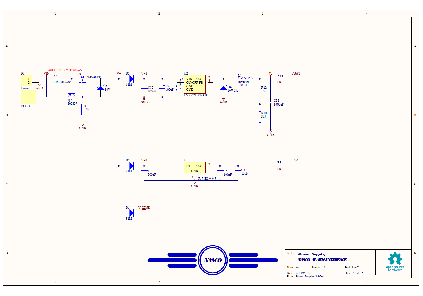
Power Supplies
The power supply for this project took a little bit of planning. The SIM900 as mentioned can sink up to 2A when transmitting (in bursts, so the duty cycle is less than 100%) and if this rail were stepped down from the 5V rail supplying the micro, you run the very real and annoying risk that 5V rail supplying the micro may sag enough to reset it - yes I've been bitten by this type of problem in the past before.
To get around this I've done the following:
- Added a big, really big, reserve cap on the SIM900 supply rail
- Isolated the 5V and SIM900 4V rails via diodes
- Also isolated the rail that supplies power to the Alarm Panel phone line and
- Realised that no way in heck this thing will run from 5V on the USB - so I've used an external 12V input
- The SIM900 needs a 4V rail so this has been provided via a switch mode regulator
- The 5V rail uses a RECOM switch mode regulator module.
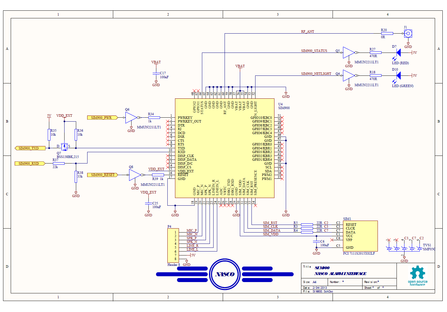
SIM900
The SIM900 circuit is basically a copy from the SIM900 application note. However, as I'm not planning on using voice with this interface I've not loaded any connectors - however I've added a header that a daughter board could use if I later choose.
Note that the SIM900 directly connects to the SIM socket and supplies power for the SIM Card. Nice and easy! Also the SIM900 has status LEDs to show network connectivity. Of course I've added these blinkenlights.

ATMEGA
Lastly, the ATMEGA32U4 is basically as per the Arduino Leonardo. The only deviation was to add a 5mm RGB LED hooked up to the Arduino defined analogue inputs - I'll configure these as digital outputs of course.
Starting Point
Now this might come as a shock to some, but rather than get stuck into a PCB design, and before the schematic was completed, I decided to chose a case to mount this in as my starting point.
Why?
Well, a lot of projects I see out there are pretty content to use a bare bones Arduino, a buch of interconnecting wires and stuff it all into a big box. That's not my preferred course of action.
Don't get me wrong - the above is a good way to prototype, but if you want it to last, fergeddaboudit. Like magic, wires pushed onto 0.100" headers will become lose, things will corrode and become intermittent - it will become a maintenance nightmare. If you want it to last, you need a good PCB, and if you want your PCB to last you need a good box for it.
I've used Hammond's 1593 Series before and chose them again. I like using Hammond as they provide full 2D drawings (.dwg files) and 3D models of their products which makes designing with them a breeze. With Altium you can import the .dwgs into a mechanical layer, and (as Hammond have the maximum pcb footprint defined in their files) you can simply copy and paste to define your PCB boundary. Sweet.


Here's the .dwg imported into Altium. It's a lot of information that doesn't come over well with a screen shot unfortunately.
As I chose to use the 1593NBK, which has a maximum PCB length of 102.5 mm, ans as I want to use Seeed Studios 100 x 100 mm PCB service, I simply trimmed 2.5 mm off one end of my board. Too easy.

Here's a screenshot of the PCB outline with the mechanical details of the case imposed. It's easy from here to align screw holes with the case posts, and get the board centred with the case.
You can also change the opacity of the 3D bodies in Altium so you can see through the case to get a good understanding of how everything fits. Nice!
One beef I have about Altium is that the design error check is a bit clunky. Well at least I can't figure out ho to get it to do what I want anyway.
The case has been brought in as two separate pieces and when you 'assemble' them you fail the clearance test. If the case model were one piece then that wouldn't be an issue - it would be a bonus as you can see when your parts clash with the housing. But right now, it's not working for me (any tips greatly appreciated!).
3D Content, Free!
As this is a 'fun' project for me, and not just a get the board out quickly exercise, I decided to update my Altium libraries. Until now I'd been content with simple blocks for my parts (mostly sourface mount) or I'd just omit the 3D part if I knew for sure that the 2D part would fit (i.e. has been used in a design before).
In my search for step models, I've found a few manufactures that supply step models. TE Connectivity are just fantastic for this. A real bonus is that Mouser carry a ton of their parts so they are easy to get too. Another thumbs up from me is for MOLEX - great for connectors.
Then I stumbled across 3d Content Central. This site is awesome. A lot of contributors with really great 3D models, that you can have for free. Wow.
So after a few days, I'd pretty much updated my libraries and my parts look great.
From this:

To this!


The guys who produce this content are just fantastic at it. Thanks to all of you out there!
So with my layout - rather than have a basic 2D layout


And it looks cool in the case too!
From this:

To this!

Some other examples include this TQFP44

.. and this trimpot.

The guys who produce this content are just fantastic at it. Thanks to all of you out there!
So with my layout - rather than have a basic 2D layout

I've now got this pretty realistic looking 3D model. The purple part is the only part I could not find a model for - A Recom R-78E5.0-0.5 switch mode regulator - but overall it's a pretty damn good starting point imho :)

And it looks cool in the case too!


There's a practical application to all this modelling too. To fund the build, I need to achieve an appropriate W.A.F. (Wife Acceptance Factor). The models help convince her that the final project wont be a big hunk of mess in her cupboard!
Thoughts and Stuff
I've tried to go with a 100% surface mount design - some connectors are through hole but the rest of the parts are SMD. Keeping the parts on the one side also will help with building it - I'm unsure if I'll hand load and solder (done this a lot before) or if I'll go for a stencil / skillet / eBay reflow oven approach. The first one will most likely be hand loaded, but with the other 9 boards from SEEED lying around, it's crying out for a mass production based technique!
To Do
If you look you'll see that the end of the case is exposed - but the case comes with end plates, and I'll need to machine these to clear the connectors. Lucky for me I have access to a PCB mill at work and when done I'll update this blog with details.
Then it's test and code time! The hardest part there will be coming up with the requirements, and nto letting scope creep kill progress. I mean, the hardware will replace the monitoring service, but add the USB port and it's crying out for integration to a full blown home automation system. I have a Raspberry Pi gathering dust at the moment....
Oh, just so that you know, I managed to build a telephone line emulator prototype and was able to decode DTMF. I'm a fan of testing building blocks before committing to a final design. The pic below shows the milled board hooked up to an Arduino clone.

One untested building block is how I'm managing protection of my power supply. The plan will be to power this interface from power on my existing alarm panel, so I want to protect my interface from reverse bias, and I want to protect my panel from overload. Polyswitches aren't just going to cut it for me.

What I haven't tried yet, but will soon, is the current limit circuit. If the current flowing through R2 is big enough to induce around 0.7V across it, Q2 will start to pull the gate of Q1 high, turning it off and reducing current flow. Well, that's the theory anyway, again I'm happy to take comment from anyone who knows better!
I've tested the circuit above. It doesn't work, so sorry if you've been bitten by this. I'll post as to why this is bad later.
Software Requirements
Some basic rules are needed for the software. For example, in my case I don't want to be contacted if only one zone is in alarm. But if I hook up a smoke detector to my panel perhaps I'll need a rule that will send a message if just that 'zone' is active.
I'll need a white board, a six pack and a free evening to draft these details with my tame software engineer soon.
Engineering is never finished, it's just stops
Refinement is always on the cards too - I've used a DTMF decoder IC as this will just work - Nick and I have prototyped this already - but the SIM900 according to the datasheet is capable of decoding DTMF. What's not clear is if it can do this via the audio inputs, or if it only works over received speech. If the former, then V2 of this can see the parts count reduced. If there ever is a V2.Oh, just so that you know, I managed to build a telephone line emulator prototype and was able to decode DTMF. I'm a fan of testing building blocks before committing to a final design. The pic below shows the milled board hooked up to an Arduino clone.

Power protection and current limiting
One untested building block is how I'm managing protection of my power supply. The plan will be to power this interface from power on my existing alarm panel, so I want to protect my interface from reverse bias, and I want to protect my panel from overload. Polyswitches aren't just going to cut it for me.

Q1 provides reverse bias protection, and Afrotechmods fantastic video explains this better than I can. P-FET Reverse Voltage Polarity Protection Tutorial.
I've tested the circuit above. It doesn't work, so sorry if you've been bitten by this. I'll post as to why this is bad later.
You can follow the series here:
Cutting Out the Middle Man
Design and Test Part 1
Design and Test Part 2
Design and Test Part 3
Implemented. Whoo Hoo!
Cutting Out the Middle Man
Design and Test Part 1
Design and Test Part 2
Design and Test Part 3
Implemented. Whoo Hoo!
great project! any chance of it becoming a kickstarter project?
ReplyDeleteKickstarter? No, not an option for us here in Oz :(
Deletenice work.
ReplyDelete+1000 to the approach of "choose the enclosure, then design around it". Sooo many projects are totally let down by leaving the enclosure until last, or going with the 'pile of wires in an Ikea disposable snackbox' look.
Hi,
ReplyDeleteGREAT Project!!!!
I'm thinking of implementing the good Lior's Project for my alarm. I will carefully follow your blog.
BR
Had too many years of others choosing the enclosure and me having to design the contents...haha! The Whitegoods Industry usually starts with what it looks like first....with no bloody concept of what has to fit inside. But it was a living...
ReplyDelete