The Nitty-Gritty (Hardware)
(This is a post in my series about my Garage Door Opener. Yes I wrote a series. About a Garage Door Opener. Check it out:
In a previous long winded post I detailed the history of how I built and installed my IoT Garage Door controller. However, that blog was light on technical details, and I'm going to cover those here.


Overview
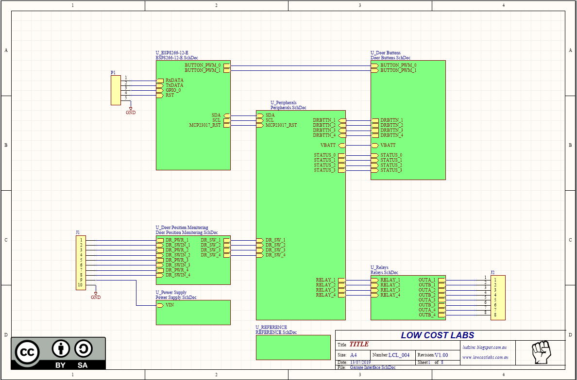
The above block diagram helps explain the architecture of my build. I like having this at the start of my projects, as it helps communicate what I'm trying to do. And it's light-years in front of a lot of open-source schematics which are just a bunch of netlabels spread randomly over a page (end rant).
So, working from the Top Left, P1 is the programming header (my bad for not labeling it) for the ESP-12 and his fans out to two other blocks - for the Door Buttons block there's two PWM lines for controlling the brightness of the buttons, and and I2C line to the Peripherals block.
ESP-12 Module

Looking at the ESP-12 sheet, you can see it's a pretty standard implementation of an ESP-12 module. There's te required pull ups for GPIO_0 and Reset (RST), I2C pull-up resistors and a reset line for the MCP23017 IO expander.
Finally, there's R7 / R8 as a voltage divider from the 12V supply rail so I can monitor if the supply rail is low. Well, I might in the future, it's not actually implemented at this time...
Note how I clamp the VSUPPLY line to only 0.7V through the use of the BAV99. The upper limit on the ADC input on the ESP8266 is 1V, and this gives a good margin of error to protect it. As it's also exposed to the outside world it is possible that spikes coudl come in on this line, and the other half of the BAV99 will clamp these negative going spikes. Nifty.
IO and Other Peripherals

Next, peripherals. As I was planning on using more IO than what the ESP-12 supports, I used an MCP23017 IO expander to cover the shortfall. I'll get more specific on how I use that later. I also have 4 on board status LEDs and those lines are also broken out to the lid of the controller where the same colour LEDs are used to show status there.
The IO expander has a fair bit to do:
- There's 4 inputs from the front panel buttons, which are used to either open a door or toggle the light control relay
- There's an additional 4 inputs that serve as 'remote buttons' - this was so I can integrate the unit with my home alarm (the remote on that has buttons that can be used to control the roller door)
- There's 4 outputs to drive the relays
- There's 4 outputs to drive the status LEDs
There's also two other devices on the I2C bus being a TCN75 temperature sensor and a DS1338 Real Time Clock.
I've found the temperature sensor to be useful, but needed some calibration to offset some self heating.
As for the Real Time Clock, it's loaded, but never tested. If I can connect to WiFi I can easily get the time from the Web, or even as an access point I can nab the time from the device that connects. So it's redundant and wont be used.
Power Supply

Self explanatory really. I've designed this unit to run off 12V for a couple of reasons.
- I have a lot of 12V supplies lying around
- The relays I have are 12V
- 12V gives a nice overhead (error margin) when operating the relays. If run off the 5V rail, when switching relays there's a risk that the power draw may cause the rail to sag and reset the ESP module.
I also use an LM2596 buck regulator to supply a 3V3 rail for the ESP module, and D1 is for reverse power protection.
However, you might want to know what D2 and D3 are for.
D3 provides a rail for the relays, that wont draw power from C1 - keeping the buck regulator supplied and ticking to keep the ESP-12 running.
D2 is there to similarly isolate the power supplied to the remote switch inputs.
Why all this effort to isolate supplies? It's almost as if this has bit me in the past before....
Why all this effort to isolate supplies? It's almost as if this has bit me in the past before....
And lastly, there's F1, a polyswitch fuse to stop any disaster burning my house down.
Relays

One of the safest ways to interface your system to another black-box (unknown) is to use 'dry contact' relays. However as I wanted to make this board dual-purpose (visions of controlling watering solenoids come to mind) I added some solder blob links so I could alter their function.

If I were to short LINK3 in the picture above, I'll have the dry contact I need to control my roller door.
However if I connect LINK1 and LINK 5, I can now switch 12V by the relay and send this out the corresponding contact. I'll up-rev my board in the near future to remove this feature as:
- Controlling watering solenoids with 12V DC wont work (they are 24V AC) so I may make a version using SSRs rather than Relays and
- I'd set up the 12V output for testig (drove some LEDs) forgot about this when I installed the unit in my garage and promptly blew up my roller door motor controllers. Ouch.

After sending my roller doors to God, I took a look at the layout - and concluded that the clearances that the solder blobs offer aren't that good and could lead to inadvertent disaster in the future. So I removed the trace between 12V and DRY. Learn from my bad, people.
Remote Switches

For the remote switches I went away from what you often see. There's many examples out there where the power rail is output on a terminal. and you run that through your button to a resistor divider onto the input of your micro.
This 'works' but exposes the unit to the following shortfalls:
- You need transient suppression. Induced voltages both positive and negative can come down the line and ruin your day. The BAV99 clamps will shunt negative voltages to ground and too high a positive spike to the 3V3 rail.
- Shorts on the rail. If you were to take the 12V out directly on a terminal, you could have a failure mode where you short the rail to ground and you'll (at best) reset your device due to a momentary powerr blip, or at worse cook your power supply / torch you board. A 22k resistor in series with 12V limits the current to a tiny 500uA, no bad can come from this!
Top Board Interface

On the lid of the controller I added 4 illuminated buttons and 4 status LEDS.
- RED: Power OK
- Yellow: External Input active (Remote button pressed)
- Green: Blinks at 1 Hz to show system is running
- Blue: WiFi connected
(When acting as an access point, the Blue LED blinks and the Green LED is on).

To achieve this, the signals from the IO expander are buffered with 470 resistors to limit current to the status LEDs or with 1k resistors to buffer the button inputs (these are pulled to 3V3 on the carrier board).
The two BUTTON_PWM signals come direct from the ESP-12 and open collector transistors are used to drive the LEDs in the buttons themselves. I used PWM as in the past I'd found the LEDs in the buttons to be quite bright.

And of course the obligatory 3D render follows.

I love that resources such as GrabCAD and 3D Content Central exist, and the abundance of 3D models you can get for free from there make these renders possible.
I've not been able to find 3D models for the push buttons I've used, so if anyone can point me at one I'd be grateful. I do know they are of the R16-530 type and googling that shows these are abundant and cheap.

R16-530

And with Dimensions. Sweet!
Riser Board
And here's the riser board for reference. The riser board carries the status LEDs and there's no passives on this board as the current limiting 470 ohm resistors are on the main board.
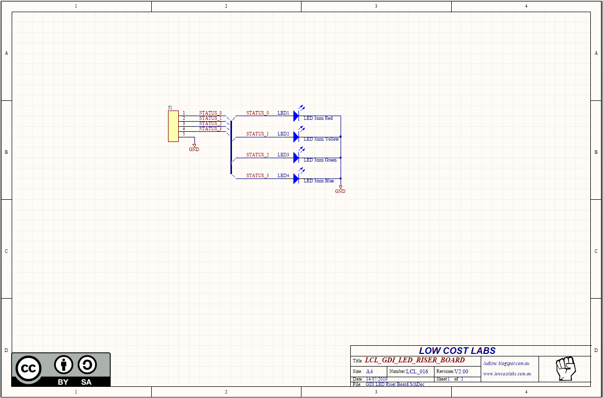

Doesn't get much simpler than this.
Putting it Together
Layout was straight forward, the third time - and it was handy that the case manufacturer had dimension details on their site. Nothing in CAD format iirc so I have some fun converting PNGs to DXFs (thanks online conversion tools!) and was able to import these into Circuit Maker and ans tidy them up. Well worth the effort and everything just fitted after doing this.

Bottom Layer

Top Layer

Case

Case Dimensions

3D Render


Assembled. Note the ribbon cable connecting the top board to the bottom board.

Installed!
This comment has been removed by a blog administrator.
ReplyDeleteThis was great, thanks for the thorough write up. Keep up the good work.
ReplyDeleteNice blog!! Keep it up...
ReplyDeleteNorton login | Norton Account | Norton Setup | AOL Mail | AOL Sign In | AOL Gold Download
Going through all of this that has been given here carefully the reader would be able to resolve many doubts and things would definitely be clearer.Process to unblock Hotmail account without verification code | AOL Mails Syncing Issue With Windows 10 Mail Application
ReplyDeleteI was worried about this topic but after reading this post I am really much satisfied as all information given in this post is reliable.How to enable IMAP in Gmail?
ReplyDeletePython raise keyword
ReplyDeletenumpy dot product
Floor function in PHP
Convert array to list Python
Convert list to dictionary Python
Count consonants in a string Python
Count vowels in a string python
Python program to add two numbers
Python program to find area of circle
This comment has been removed by the author.
ReplyDeleteAbsolutely impressed by the meticulous hardware breakdown! The attention to detail in circuitry design and component selection is admirable. Kudos for integrating safety features like transient suppression and isolating power supplies. For those who wants to avoid DIY and are seeking top-notch garage door solutions, I highly recommend CR Garage Doors – you can get innovation and reliability at its finest.
ReplyDeleteThank you for breaking down the technical details of your garage door opener project. It's amazing how much thought goes into each component to ensure safety and functionality. This post is a great resource!
ReplyDeleteHelpful tips and detailed service info. click here for more information.
ReplyDeleteGarage Door Repair Services
Looking for reliable garage door repair Queens? Master Garage Door & Gates provides same-day service, expert repairs, and affordable rates across Queens.
ReplyDeleteReally enjoyed reading this breakdown of your garage door opener setup—it's the kind of practical, hands-on detail that helps others understand what to watch out for with their own hardware. I’ve been exploring upgrades for my garage recently, and posts like this make the process feel more manageable. It also reminded me of how Manmachine Automotive, a leading garage makeover company in India in India, emphasizes the importance of getting the basics right before any major renovation. Thanks for sharing your experience!
ReplyDeleteWhen you need garage door repair service, you should call us. With this in mind, we provide affordable prices and outstanding garage door repair services.
ReplyDelete