BASIC PROTECTION
For a recent project I'm working on, I wanted to add some basic IO protection. The requirements for this were:- As usual, it had to be cheap
- It had to be bi-directional. The pin to protect was configurable as either input or output.
- Provide short circuit protection
- Provide over-volt protection
- Provide reverse bias protection
- It also has to be cheap
OPTIONS
There are many varied options that could be used. Some options I considered included
- Do nothing
- Using a P-FET
- Voltage Clamps
- Polyswitch
- Buffer Circuit
- Zener Circuit
Do Nothing
Not the best solution all the time, but sometimes quite suitable. For my application, no dice. But if you are basically making a fixed connection that's never to be disturbed, is safe inside a box and is over a short distance, knock yourself out.
P-Fet
This I must admit is a favourite of mine. It's just plain neat. Rather than go on about this too much, check out Afrotechmods fantastic video about it. P-FET Reverse Voltage Polarity Protection Tutorial
I didn't go with this option as I wasn't sure about it's operation as a bi-directional device.
Voltage Clamps
I've used this before, quite a bit and I like this as it's quite useful, cheap and easy to implement.

Shown above is a typical arrangement that I've used from time to time. The BAV99 is a SOT-23 package that carries dual diodes, rated to 100mA continuous, with 1A surge. If the input voltage is around 5V the current to the system you are protecting is limited by R1 to approximately 10mA. However this is dependent on the impedance of the sink, and if (for example) it's an input to a microcontroller, the impedance is very high and very little current will flow. This will be important later.
Overvoltage protection kicks in for voltages greater than VCC plus a diode drop (e.g. 0.7V). For example if your connect the input to 12V, the top half of D1 conducts, and you end up with 6.3 Volts across R1, and conversely about 13mA flowing through D1. If Vin is negative, the bottom half of the BAV99 conducts saves your micro's input pin.
One problem is that you need to route voltage and ground to each clamp, and if your design is densely packed, actually making these routes could be a problem, and that's why I ruled out it's use in this project.Beware the Polyswitch
Oh God how I hate these.
On the surface, the idea of a resettable fuse is brilliant. With respect to my requirements a polyswitch only provides short circuit protection, and offers nothing for reverse bias or overvolts. That's fine, and that's not my grudge.
With Polyswitches, you need to have a good look at the datasheet to appreciate just how evil these things are. Here's an example.
Say you want to limit current to 50mA. A quick look at the above datasheet might have you selecting the 0603 sized femtoSMDC005F which on the surface looks like a winner.
But if you take a look at the 'Time to Trip' curves, you might rapidly become horrified..


I've modified the chart to show a few things. The red line is the rated current of our selected polyswitch, 50mA. You will see that we never cross the A curve, so in effect at 50mA this chart tells us that the polyswitch will never trip. Which makes sense, you don't want it to switch at 50mA, all is good.
But take a look at the green line. I've placed this at a time to trip of 10 seconds. You can see that the green line crosses the A curve at a point that equates to current of over 100mA (it's between the 0.1A and 0.2A lines on the curve). Or in other-words, at 100% over rate, the polyswitch will take up to 10 seconds to trip.
This is guaranteed to let the magic smoke out of your delicate circuit you are trying to protect.
Okay, I might be a bit harsh in my assessment of the polyswitch, because I wouldn't use a 50mA fuse to protect a delicate circuit either, as the exact same problem exists with these.
If you have a sudden drastic fault and you overcurrent by a massive amount a fuse or polyswitch will save your bacon. But for a 100% circuit killing over rate, you're screwed.
A good rule to remember, is that the fuse is there to protect the cable, not the device (otherwise nasty short circuit currents will set fire to your cable / home).
So for my requirements, polyswitches are out.
Buffer Circuit
There are some excellent bi-directional buffers out there, but in this project I was very space constrained. This ruled those out.
Some other pros / cons with buffers. If unidirectional you lose the ability to configure your IO pin. If the application is fixed, this doesn't really matter, but as I said I needed to be able to configure my pins on the fly.
Zener Diode
This similar to the voltage clamp, but without needing to route power to each device.

It's almost so simple it just has to have a catch... and this time it caught me out. As in my schematic above, I used a BZX384-B5V1, which is a 5.1V Zener. I was in a hurry, and went with what was available. I mean, how hard can this be?
A quick look at the datasheet shows this device as rated at 5.1V with a 5mA test current. My mistake was in thinking 5mA test current is close enough to my limit of 10mA so all should be good.
But my mistake is that the Zener is not conducting 10mA in my design. As I mentioned before I'm protecting a pin on a micro which is a high impedance, and as the Zener is also a high impedance there's actually very little current flowing in my resistor / Zener combination. So what's the big deal with that?
If you look at this curve from the datasheet:
.PNG)
you can see that the Zener shows a turn on characteristic that's a smooth curve versus a discrete step.
If you zoom in on the chart,
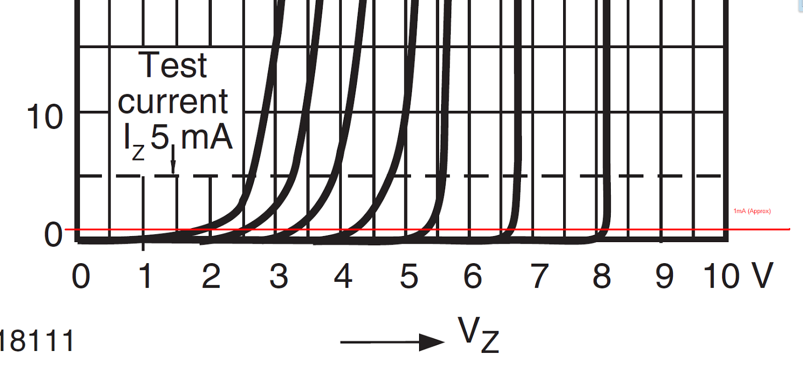
You can see that the mA scale has graduations of 5mA, so trying to interpret how these devices will operate at currents less that that is pretty much guesswork. I added a red line that I 'eyeballed' to be less than 1mA and you can see that below this line you have quite a lot of variation in the curve. The 5V1 curve isn't actually there - 4V7 and 5V6 are so you again guess that the 5V1 curve lies between these curves and act the same way.
If you look at the 4V7 curve, the Zener voltage is as low as 4.1 or 4.2V. For the 5V1 part I'm guessing it will be '4 and a bit volts'. Experimentally it was worse.
Applying 5V to the input, the output measured just on 4V, from a 5V1 Zener. Nuts.
However there's a redeeming feature here. I was driving a TTL input, and the high level is well defined as greater than 2.0V, this will work. But it's not brilliant, but that is the trade off for price.
Summary
All in all, it's a case of once again knowing what you need to achieve and how it can be done. The Zener protection circuit I chose will provide protection, but mostly from the series impedance, not the Zener. What the Zener will do is clamp over volts and spikes coming in the line, but in normal operation it actually will degrade my logic levels. But it will still work and it's also cheap :)
Wow nice article, it point me in the right direction!
ReplyDelete