Did I mention he own's his own Cafe and wants to roast 10kg's at a time?
Funny thing is, whenever he got into a conversation about making his own roaster, just about every time someone would say 'That's Awesome'. So the mighty roaster was named.
AWESOME

Told you it's Awesome!
Probably not the way you'd usually write up a build story, but lets start with the finished beast first.

Oh Yeah. Ready to Roast.
I was lucky enough to help Mark with a few jobs on this roaster. My little MIG welder took a hammering, I designed the electrical system (but this was installed by a proper sparky), drew up the control panel metal work, but my favourite part was working on the blue numeric displays.
There's a fair bit inside the roaster, but the interesting part is that the fan that blows the hot air through the green beans, and the speed that the drum turns are speed controlled. The little yellow boxes below are fed a speed input from a trimpot (a 0 - 5V input with 0V being your minimum set speed, 5V your max), and they run your motor at your chosen speed.

We Have Control
These speed controllers are pretty neat - you can programme the upper and lower run speeds, and they output a speed signal that runs from 0 - 10V for min / max speed. Nice.
Mark wanted to display these speeds, and we looked around for some off the shelf displays, and most of them came up short. So I thought I'd cook up a batch of my own. The nifty part is that I can modify the firmware to suit each motor - they both have different max / min speeds so for the same input voltage each display needs to show a different speed. Fair enough.
Mark also needed an elapsed time timer - and it pretty soon dawned on me that the same hardware could provide the timing function. Sweet.

Prototype Fired Up
The above picture shows the initial power up test for the display. I hadn't sorted the firmware yet so I was just running some test code - the speed displays (top and middle) were just showing raw ADC counts, and the bottom display was just a fixed seconds counter (the small green / red buttons to the right of the display are to start / stop the timer).
MODULE DESIGN
As usual with anything I build, cheap is good. Raiding my stocks I found I had some PIC16F88's and PIC16F627's lying about. I really like these little chips - they are pin for pin compatible, both run internal oscillators (keeping parts count low) and run on 5V. The F88's have a 12 bit A2D, making them perfect for reading and displaying the motor speeds. As I only had two of the F88's to hand I used a F627 in the timer as I didn't need A2D for the timer.
Of course, I had the F627 as an available Altium Library figure so that's what was used in my schematics.

Display Module Overview
Yep, I have access to Altium at work, and as I've been using it since it's Protel Days, that's what I use for my home projects. Sorry to all the Eagle fans out there - but I do believe there are Altium to Eagle conversion scripts out there.
Anyway, as can be seen above, it's not too complex - There's some inputs, a liner regulator a microcontroller section and the all important display block. As the speed controllers output 0 - 10V, I've used a divider on the input. This is actually pretty helpful - the 10k of impedance to the micro's pin provides a heck of a lot of protection from stray signals, and with the internal clamp diodes on the PIC's input pins, you have a pretty robust design. Inside something industrial like this roaster, there are plenty of induced voltages that can ruin your fun.
Even though I needed only one input to display speed, I needed another input for Timer functions - one for start, the other for stop. Pretty easy to add at this stage.
As an aside, I always cringe a little when I see a new starter hooking up signals to an Arduino without any protection. On a breadboard when you are learning, that's fine, but when it's used in a final installation, don't be surprised if your project has a short life....
MULTIPLEXING FUN

Display Multiplexing
Here's where I made my first mistake. To keep the number of IO lines down I decided to multiplex the 7 segment displays. No problem there really, it's been done 1000's of times before, just not by me...
To make coding easier, I decided to use an MC14543 BCD (Binary Coded Decimal) to 7 segment display driver IC. Just output your number as a 4 bit nibble, and the MC14543 turns on the right LEDs in your 7 segment display. It also latches the output, so you can change the input and not screw around the output. Nice.
And this is where I dropped the ball.
I used only the one MC15453 - tight arse, remember - and pulled the anodes of the 7 segment displays low in turn. What this means is that I can only light up one 7 segment at a time, and with 4 in the system I'd limited myself to a maximum 25% duty cycle. Yep, I'd cleverly set it up so I'd be forced to run my displays at quarter brightness. If I were ever to do it again, I'd use an MC14543 per 7 Segment display, and then be able to wring out the maximum brightness of the displays.
Fortunately, the 7 segment displays are pretty bright and even at my munted quarter strength outptu they are perfect for use in the shop. Phew. The real irony was that I was planning to implement PWM control to dim the displays as I was afraid that they would be too bright :)
You'll notice that I used MMUN2211's to switch the 7 segment display anodes. These little beauties are 'pre-biased transistors' and save you needing to add base and pull down resistors, all in a SOT23 package. Nice.
For completeness, here's how I set up my IO for my micro, and my garden variety 5V power supply.
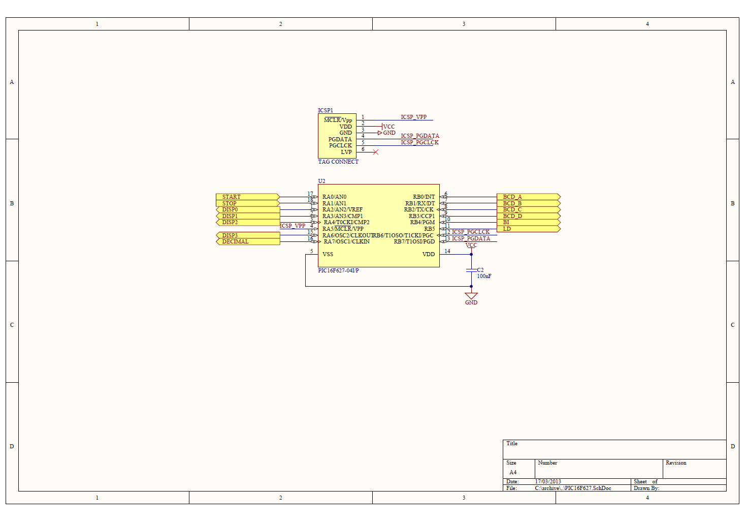
Micro Control

Power Supply
If you're keen you can get all my Altium Design Files from here. With errors still in place too!
MAKING IT HAPPEN
Along with my stuff up in design, I also ballsed up the implementation. In my haste, I punched out this simple PCB design in a short evening, and ordered the PCBs (love SEEED Studio). When I assembled them a short time later, I found that I'd forgotten to actually connect the 7 segment display's anodes to the pull down transistors. If I'd submitted a design at work without running a Design Rule Check (DRC) first, I'd be in big trouble. But when it's my money, meh....
You can just pick the unconnected rats nets in the 2D pic below -

Can you see me?
But there's no missing the Tinned Copper Wire (TCW) on the units below.

D'oh.
And here's how the 3D renders in Altium compare to the real boards above (which I'd only just started playing with at the time).


I'm also a big fan of Tag Connect - you can see the programming header footprint on the boards above. I love the fact that it's a zero cost to you (it's just holes and PCB artwork), but as I knew I'd be programming these boards when they were hanging inside the roaster I used the clip in version. Nice, but not perfect and I'll share my thoughts on that later.
FINISHING UP
Once assembled, code was cut and the boards tested. Skipping over the initial test code (very basic lights on test) I was soon confident that my code was ready to go.
With the machine up and running, the displays would 'flicker' in a very annoying matter. Basically, noise would cause the display to increment / decrement it's speed display constantly. Fore example if running at a steady 1200 RPM the display would change from 1198 to 1201 and back to 1199 etc. Annoying.
Like all good hardware engineers, I fixed this in code. I hard coded some hysteresis in - basically if the calculated display output varied by less than a set amount, I didn't let the code update the display. As crude and clunky as this sounds, it resulted in a very user friendly interface. Most importantly, Mark was happy with it's performance.
Timer Improvements
The timer code also had some last minute improvements. It initially only had basic start (green button) and stop (red button) functions, but I quickly realised that an operator might want to reset the timer to zero *without* having to power cycle the whole roaster. D'oh.
The fix was pretty simple. To reset the timer, you just press the stop button a second time! Effectively the first time you press the stop button you simply pause the timer, and if you want to reset, you press stop again - or if you want to continue timing press start again.
Lastly, the timer needed a little HMI (Human Machine Interface) improvement. The timer counts in minutes and seconds in a MM:SS format - pretty standard fare. When first powered up / reset the display showed 00:00. When you then press start, it felt like nothing happens as the display stares at you showing 00:00 for the first second of operation - and when you're testing stuff like this a second is a heck of a long time!
The simple fix here is to make the display blank the first thee characters. When you press start 00:00 turns into a single 0 so you get feedback that the timer has started. The quick and dirty way to blank a character using the MC14543 is to write an illegal character to it, and that's what I did. Too easy.
And if you're interested, code for both functions can be found here.
MOVING ON
 |
Success! The 12,00th Roast. Woot! |

The Coffee King and I
If you are ever in Adelaide, you should check out his shop. If you can't do that, you can order his coffee from his website.

How's the coffee? AWESOME.
very cool project, I would like to know where you got the buttons/leds on the left of the 7 segment displays
ReplyDeleteI second this button comment. The buttons are awesome, I wants them!
DeleteAlso here, those buttons look sexy!! nice project.
DeleteFYI
ReplyDeleteThese are the illuminated switches that I used:
http://au.element14.com/schurter/1241-6664-1122000/switch-250-v-gn-ring-ill-30-mm/dp/1212117
http://au.element14.com/schurter/1241-6664-1121000/switch-250-v-red-ring-ill-30-mm/dp/1212116
They are very expensive, and I was bummed that the illumination was 6 distinct points of light, rather than even illumination as per the Element 14 pics above.
Cheers,
Simon
http://www.thecustomsabershop.com/16mm-Anti-Vandal-Latching-Red-Ring-Switch-P413.aspx
ReplyDelete$12
could have run it through some transistors to relays if needed for the higher rated switching.
I used a similar (non-latching) switch for the timer buttons. The other buttons are 32mm in diameter - big suckers.
DeleteFor $100, you could have had a machinist make you a few
DeleteI'd love to meet your machinist!
Delete