Well, Halloween, anyway....
Growing up there was a saying in our house. Dad, when pushed for a deadline, would quip "By Christmas." If Christmas beat Dad to delivering the cubby house / painted kitchen / whatever he'd promised, he'd simply state "I didn't say which Christmas...."
At the time, that saying annoyed me. These days, I hide behind it!
2015
2015 bought a lot of promise, not limited to just hoverboards, but more excitingly for me, Altium had promised to release Circuit Maker, their free PCB design tool, targeted for hobbyists.
Naturally I was a little bit impatient....
Anyway, Altium got their act together and in May went to Open Beta. Woot.
Now to truly test a CAD programme, you need a project. I happened to have a few tubes of PIC16F648A's lying around, and I've wanted to experiment with low power battery operated devices, especially with the aim to see how low a sleep current I can achieve.
So, with micros, jelly bean parts, LEDs and lack of inspiration, I asked the kids if there was anything I could make them. My youngest came up with the idea of a Halloween Badge. That being 5 months away, I was confident we could get something sorted.
I'd also used 'Top Mount' LEDS in the past, and knowing that FR4 can be translucent, thought that shining orange leds through the boards might be a good approximation to a candle.
At the same time I started punching out a LED Heart trinket, to sort out Valentines day as well...
So armed with some random clipart from the web (which I can't find now, sorry!) I knocked this up in Circuit Maker.
Time Keep's On Slipping
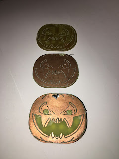
Okay, I've skipped over a bit... What I've shown above is the final revision. I started with a prototype design that I could mill at work and start developing code with. I've never had to do effects with LEDs and again, this project was a great opportunity to learn.
However, by the time I'd milled and coded these...
First Prototypes
Job Done, Recycle the Bits!
.. Christmas was already upon us. Oh well, Halloween 2016 here we come!
From the pics above, you can see that I originally thought I'd use a single sided PCB, with the pattern engraved in top layer. However when I milled it, I screwed the registration and had to start again - but I only had double sided FR4 left in stock.
It was then that it occurred to me that I could selectively remove some copper to let the LEDs shine through the eyes and mouth parts for effect. Nice. Note that my first prototype used standard 0603 LEDs as I was waiting on delivery of the Top Mount LEDs, and I wanted to get cracking on the code.
With the arrival of the Top Mount LEDs, the above prototype was assembled *and* I finished building my Simple Current shunt amplifier (for measuring low currents typical of a sleeping micro).
Of course, there were mods to the prototype. In an effort to minimise part count, I used the internal pull up resistors of the PIC16F648A (hidden under the coin cell holder) to bias my 'mode' switch, which is active low. With my super hi-tech test setup ready,
.. I soon saw that the operating current was around 2.5mA (when running a LED pattern), and a sleep current of 10uA. Wow, not bad I thought!
(I don't have a picture of the uA measurement - in that case the smaller meter, measuring milliamps in series above, was removed. The larger meter is measuring mV coming out of the current shunt amp - where in the mA case it's 1mV/mA and in the uA range it's 1mV/uA).
But when you look at the capacity of a typical CR2032 cell is around 200mAh, that's not great.
200mAh / 10uA = 2000 hours = 83 days, or almost 3 months..... eep.
Looking at the PIC16F648A datasheet you can see that the weak pullups alone consume typically 200uA.
It's hard to tell from the pic, but the mod made was to add a pull down resistor to my button and wire the normally open contact to VCC. Also, I had just about every peripheral in the micro enabled, so if I didn't need it, I turned it off in the code configuration. With those mods made, sleep current fell to 4uA. This gives a standby life of over 5 years! Woot, Job Done!
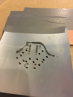
With the prototype sorted, I ordered some updated PCBs and cranked out a solder stencil at work.
Again, it was time to try some new stuff. I applied paste to a group of boards,
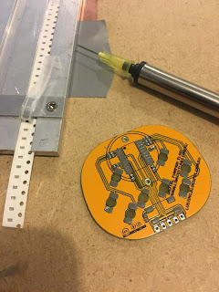
and placed the parts using a $20 eBay vacuum pencil
Once the parts were placed, it was time to crank out the hot air soldering gun.
The hot air was proving a little too slow, so I stepped up to using an electric frypan. Worked a hell of a lot quicker, but I didn't video that!
Soon after, I had 13 pumpkins ready to roll. The kids can wear them as a badge by simply placing a magnet behind the coin cell with their shirt between them.
Box 'o Pumpkins ready to go!
Finished Items.
Once the kids saw the pumpkins, they wanted other trinkets - Christmas Trees and Valentines Hearts. So they got punched out too!
So, I'm all ready for the next Halloween, Christmas and Valentines. Finally!


No comments:
Post a Comment