Double or Nothing!
As I talked about last time, in my last Seeed order I organised multiple designs in the one PCB service. In this blog I want to let you know how I went from this:

Two for One
To This!

Getting Jiggy With it
There are many options when it comes to cutting up PCBs. You can slice them in a guillotine, cut them by hand, slice them with a Dremel or score and snap. Don't ask me about V-groves, I hate that.
And all the above takes a truck load of time, and is really, really hard to do consistently. If i was just going to hack together a prototype I'd not care, but with 12 pairs to separate (yes, Seeed gave me x2 bonus boards!), and with access to a PCB mill at work, I decided to get a machine to do it for me.
I've used this mill at work for over 5 years now, and one thing that's impressed me with it is it's repeatability. If I've milled a board, and not got the depth of the cutter correct, I just wind the cutter down a tad and re-mill. With this 0.008" tracks and spaces are easy, and I've pulled off 0.006" before as well.
So, the plan in my head was to use the 2mm end mill to machine away the material holding the two pcbs together. I'd chosen to try this when I laid out my boards - hence the 2mm separation between the boards. And to do this I needed a way to place the boards to be milled in the same place each time. This I hadn't worked out how to do yet.
Below is the end result with my first separated pair.

Separation achieved.
LIMITS
As the LPFK mill works with 1.6mm stock, my reasoning was that I needed to build a jig that would hold my target boards, be easy to get my boards in and out, and provide good registration for the repeated mill cuts.

Mill ready and waiting
I've actually tried this before with another design, and all I did then was to cut out a blank the same size and shape of my PCB to be milled, and went to drop it in. That didn't end well.
The board was a tight wedge fit in the hole and thus I took to the hole with a file to open it up a bit. Long story short, I can't file to save my life and that attempt resulted in a Jig that was so sloppy I might have jsut cut it with a hacksaw...
So with that lesson learnt, I came up with this pattern to hold my boards.

Jig Outline
The Jig works like this:
As I wanted to mill along the x-axis (with respect to the above figures) I've cut out the profile such that it makes near full contact with both the top and bottom sides of the board - this is so that the boards can resist separation when the mill runs through them.
For the ends of the boards, I made reliefs in the jig so that the ends are only held in place by the little lumps shown. The corners were 'expanded' to allow the edges to fit. This probably wasn't needed as my boards have rounded corners, but if they were standard square boards this would be mandatory.
The software (CircuitCAM) I sued came with the mill - it imports your Gerbers, and the exports LPKF mill friendly machine code. Out version is quite old and clunky, but it gets the job done.
The picture below shows the tool path for the 2mm end mill - I intend to cut out inside the yellow boarder.

Mill Path
Once done, the output from CircuitCAM is then imported into BoardMaster, which is used to drive the mill. The picture below shows this job with the milling path highlighted in yellow.

Milling Path
Once loaded, I jog the mill head to the extents of the work path to make sure it will fit on my PCB stock. Kind of embarrassing when you break out into a void left behind from a previous project. It's also expensive when you let the mill bit run into the hardened steel location pins...

Good to go.

Done.
After milling, the 'negative' of the jig is pulled, and the target board was test fitted.

Test Fit
So far so good - from first impressions it looks like a good fit, but I was still worried about the board moving during milling. Not obvious in the photos is that the board could be wiggled about in the jig. However some judicial application of the Engineers second best friend and all wiggles were removed.

Sit. Stay..... Good Board!
SLICE AND DICE
With the jig sorted, it was time to programme the machine path for the mill to part the boards.
To do this I defined rectangular perimeters that matched the profiles of the boards I wanted to separate.

Right down the middle
Again, this was programmed in Circuit CAM, and is shown in the picture above. Note I moved the previous board outline to the top layer so I readily tell these apart when working in Board Master.

Ready to Place
By default, Board Master drops your new job into the middle of the work space. As you can see above, the two jobs aren't aligned. The one in the bottom left is the job that milled the jig, and the one in the cnetre is the one that I want to use to part the two boards.
Fortunately, as both jobs have the same outside dimensions, it is easy to move them to the same position - you edit the placement of the boards by simple copy and past of the X-Y coordinates - see the dialog below.

By the numbers
The two overlapping jobs now look like this.

Milling Defined
The two job s now exist in the same location, and the mill path is defined by the bright yellow line. The bright yellow highlight is where I have manually selected just this path for the mill to run. What I could have done to speed up the operation was to delete the original job (the jig profile) and then I could just 'select all' on the milling layer rather than manually selecting this path. This didn't occur to me at the time, and as I was able to mill out each pair of boards in under a minute, optimisation wasn't on my mind at the time...
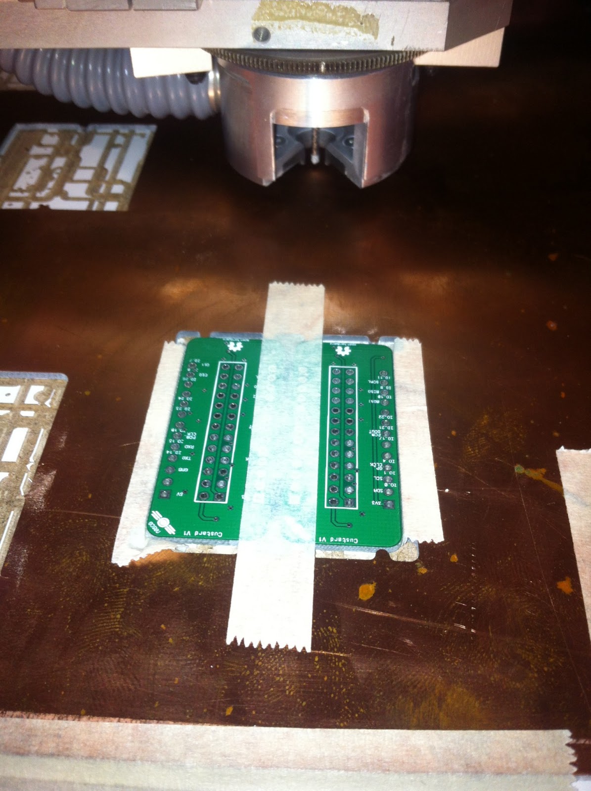
So, it was time to see if I had ballsed this up or not. As Seeed gave me and extra 2 pairs of boards, I could afford to make a few mistakes.
First Cut

Nearly There
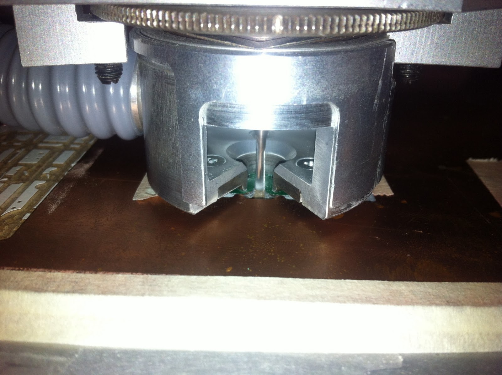
These two pictures show the cutter - the guard was open only for the photos and I swear it's always shut any other time.

Success
And it's done! Although the above shot looks fully successful, there was a brief moment when it all nearly came to grief. The LPFK mill has a vacuum attachment that pulls all the swarf away when cutting. This little feature is well worth the extra noise of the vacuum cleaner!
However, and the cut approached the end of the milling path, the vacuum picked up the boards - thankfully as the mill is surrounded by a collar that contacts the PCB being cut, there was only a little wiggle of the boards being cut and thus the cut isn't 100% straight. The boards didn't lift off the milling bed, but rather the free ends twisted together. I'm probably not doing a great job of explaining what happened - if you look at the picture above, and imagine the milling bit at the top of the picture between the two boards, you can see how the bottom of the two boards turned towards each other.

11 to go
All in all, I was damn happy with the result. The wiggly cut was still a *lot* better than what I could do by hand, and it didn't stray into the track work so the boards are still useful. I did want to do better, and a simple idea popped into my head.
Extra Wiggle Proof
Yep, told you it was the Engineers second best friend.

Done.
The mill is suitable for FR4 fiberglass, so I guessed that masking tape would not present any problems. Yes, it might leave some residue on the PCB's - but as I always clean my boards before soldering, it's no big deal. The mill bit did look a little gummy after the cuts (you can see the tape glue stuck to the mill bit in the above shot, if you look closely) but while cutting through FR4 the gum seems to be cleared quickly.

All cut
Once I'd cut out the second pair, things progressed quickly, and 15 minutes later all the boards were separated.
Woot!
From here, the next step will be to assemble and test (and then blog!). So right now I have a short wait until Mouser delivers the parts, but I'm pretty stocked that I have 24 boards, for less than ten bucks. Fourty Two cents each. Yeah, pretty happy about that!
To the right of this picture you can see the pile of bus controllers that I also separated - lots of assembly to come.
No comments:
Post a Comment