Getting Jiggy With it
So, about three years ago(!) I rigged up a controller for my roller doors, and my daughter mentioned that it would be cool if I could open them using my phone.
My initial thoughts were to use a Bluetooth to serial adaptor and just use a keyboard app to send an open command.
And after getting delivery from eBay of a great HC06 module, I realised I was screwed by Apple.
No my iPhone 4 wouldn't connect to the HC06 and I wasn't going to upgrade my phone to take advantage of Bluetooth Low Energy either.
So I went searching for a solution that would work, not just on my phone, but on any mobile device. This is part of the story as to how I got there....

This will not do at all...
Enter the ESP8266
At around the same time the *awesome* ESP8266-01 module became available. As it supports a full Built-in TCP / IP protocol stack, it's a 3V3 powered web server with IO that can be used to open my door from any thing with a web browser.
Except I had no clue how to programme it!
Thankfully there is a ton of information on the web for getting an ESP8266 running, but I found Rui Santos' tutorial to be an excellent starting point.
Anyway, a long story short I managed to get my prorotype up and running using breadboards and after managing to destroy three ESP8266 modules do to stupid wiring errors, I finally got around to building a robust Programming Jig.

And here it is!
Circuit Making
In the past I've used Altium for my projects, and this makes sharing projects difficult. Altium now have a free (cloud based, nothing's perfect!) product called Circuit Maker and you can find my Jig design here.
As I was going to mill this board at work, I stuck to a single layer design, and bitter experience has taught me that soldering wire links on these is a royal pain in the ass, so I was quite happy to punch this out without any.

Look! No Links!
Actually, the above is a little lie - that's not the board I milled. I added some links on the GPIO lines after milling, and I don't have a screen shot of 'before'. but still, no links!
Toner Transfer Fail
I decided to try something new here (as I do with most home projects) and as I've never tried toner transfer before I thought I'd give it a whirl by trying to add my top layer silk to my milled boards.

Looking promising...

You can say it didn't work well at all...
There's a lot of reasons why this didn't work, the most likely being that my printer doesn't print heavily, not leaving a lot of toner to transfer. Might try different settings later, but might not too...
But still- my single layer design is out there if you want to roll your own board at home. Enjoy!
Keeping it Simple
The Programming Jig isn't the most complicated widget inn the world. What it needs to do is pretty simple
- Provide a TTL Serial to USB translation
- Provide a 3V3 Rail
- Provide the ability to hold GPIO_0 held low during reset (to enter programming mode)
What I also added was
- LEDs connected to GPIO_0 and GPIO_2 to help development
COMS
To manage the USB-TTL translation, I planned on using a PL2303 module from eBay, and at under a buck-fifty, I can't get the parts for that. A 5 way header on the board made for an easy connection.
POWER
Although the PL2303 module has a 3V3 output on it's pins, it's not powerful enough to run the ESP8266. Some people have reported differently, but at a buck a peice, these LM2596 modules are what I use as 'order fillers' and it was a no brainer for me to use one (and add the external power input connector).
Keeping Up My Reputation
In my rush to get a working jig, I made a noob mistake. I hooked up the ESP8266 Tx line to my USB modules Tx line and also the same with Rx / Rx. If hooking up a module with flying leads it's no big deal, but I wanted to solder my module in place.

The pic above shows assembled, untested boards, and then I went to test I noticed that Tx LED on the USB module blinked when the ESP8266 was powered up. Yep the data the ESP spits out at boot was hitting the USB modules Tx line and that isn't going to work.
So a little PCB track surgery and some wire links later, I was in business.
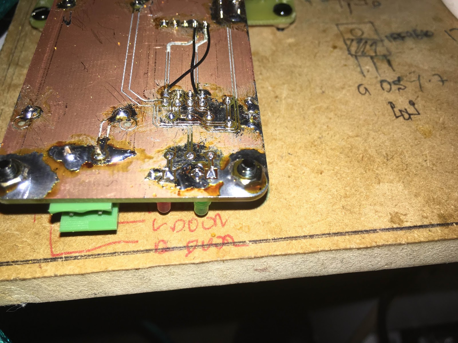
I also soldered the mounting nuts into place. That will let me take the screws off and have non-scratch low cost robust mounting feet. Woot.
Getting the Job Done
My next step was to update my board to fix the Tx / Rx SNAFU, and while at it I added some headers so you can disconnect the LEDs from the GPIO lines, giving you a board that's useful for both programming and lets you break out the IO for prototyping.

The Simple Schematic

I also forked the design into a double sided design, with a pluggable header for the PL2303 module so you don't have to muck about removing the modules header so you can solder it into place. I'll get some boards in my next PCB order so hit me up if interested.
Serial Fixing
One trick I learnt a long time ago, and failed to use in this build, is to use a pair of jumpers in-line with your Tx and Rx lines.

When routed as shown above, you can either install the links horizontally to let the signals "flow through" as expected, or to install them vertically swapping the end points. Much easier than cutting tracks when you get your Tx and Rx mixed up!

At the end of the day, I got my jig working and I was able to finish my next-generation garage door opener. But more about that later.
No comments:
Post a Comment