Final Tests and Code
Listening to Others
I've made no secret that I took my inspiration from Lior's Alarmino project, and I was quite pleasantly surprised when he contacted me on one of my posts. He suggested that I take a look at the value of the filter cap I'm using on the 4V rail supplying the SIM900.In his design, the bulk storage cap was charged by a linear regulator that delivered a maximum of 1A, but as my design uses a switch mode that's (nominally) rated to 3A I figured I could go smaller with my filter cap as my circuit can deliver a higher rate of charge - even with the substitution of the eBay sourced LM2596 circuit.

Thank You eBay!
It's All About the Power
Even though the LM2596 can deliver 3A (12W at 4V) I have to take into account that I've fitted a current limiter to the input circuit of my board. With a 500mA limit and a 12V rail, I've only a maximum power budget of 6W, and if you account (guesstimate) for losses in the system, I could be down to around 5W to the SIM900, and at 4V that's not a heck of a lot more above 1A. Lior could just be onto something here!
So I stripped parts from the external regulator board, and fitted them to my board. My old inductor was a fair bit bigger than the new one, so I had to add a length of link wire to get it hooked up - but hooked up it is!

Made to Fit
Next, in case I screwed up, I removed the link on the 4V rail to the SIM900 and powered up. No, it didn't work, my 4V rail was a crappy 1.6V. How hard can it be?
Reading up on the application circuit in the LM2596 datasheet and running the numbers on the ratio of the feedback resistors, my 10k / 33k combo was way off the 1k / 2k2 required. So a quick resistor substitution later, the 4V rail was up and running, and it was time to turn on the SIM900.
This resulted in the resetting the micro. Son of a.....
The reason here is that the SIM900 is a hungry unit, and when it starts up and sinks a ton of current, my 5V regulator is momentarily starved. I'd diode isolated my 5V regulator, and added a decent filter / reserve cap on the 5V output, but only had a 100nF cap on the input.
Not visible in my pictures, I fitted an additional 10uF cap on the input to my 5V regulator and this kept my 5V rail steady during SIM900 startup. Success!

All Lights On - A Good Thing!
Measure It!
So, time to check out how it measures up. I hooked up some scope leads to the 4V rail and fired up. Channel 1 was connected close the the 1000uF cap, and Channel 2 is right on the 4V input pin of the SIM900.
The reason for this is the 1000uF cap is a 'bulk' cap and will 'work slowly' where the 100nF is a 'fast' cap. The traces between the two act as parasitic instructors and theory has it that the 100nF will keep the rail up until the 1000uF can kick in. By scoping both points, I was hoping to see some real world differences.
The following plots from the scope are Channel 1 (yellow) and Channel 2 (blue) AC coupled and set to 200mV / Division. Although the dips are real, I don't see any difference between the traces. Fair enough, carry on.
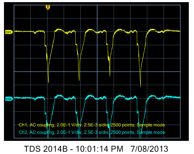
Dips are Real.
When active the SIM900 sinks power in pulses of 0.577ms each 4.615ms - and this aligns well with what we see above. As the traces are AC coupled, and the voltage divisions are 200mV, you can see that the 4V rail dips almost 800mV leaving 3.2V to power the SIM900. The absolute minimum voltage on the SIM900 is 3.1V so this isn't good at all.
Rummaging around, I found a 1500uF cap so this was fitted in parallel to the 1000uF on the 4V rail (for a total of 2500uF). Repeating the test the dips on the 4V rail were dramatically reduced - to only around 20mV - so there is now sufficient headroom on this rail to keep the SIM900 happy. Thanks Lior for the tip - this investigation now has saved a lot of future heartache in the future!

Reduced Dips - Win!

Extra Cap Fitted

Lid Still Fits!
The SIM900 has some built in status lines and hooking LEDs up to these give you a nice indication of operation. In the Video below, Green = SIM900 is turned on, and the Red = network status. If it blinks every 3s, you're connected.
Running.


Ready to be put into service.
It's In the Detail
While the temptation was to leave the board as is and call it done, I'd made a promise to myself to 'finish this one properly'.
This meant that I couldn't leave the ends of the box open, I needed to make some end plates.
Working from the dimensions in the excellent Hammond drawings (see 1593NBK), it was a lunch time exercise to lay these out in Altium.

The RJ12 connector I use is a tight fit in my case - in fact it rubs against the lid. Thus the cut out as shown above.

You might notice that in the past I showed two leds near the antenna. These are the status LEDs from the SIM900 module (labelled NW and SIM above). For system status I used an RGB LED internal to the case, and frankly that's stupid. When the lid is on, I can't see the status. So I added a third 5mm hole (labelled STAT) and relocated the RGB LED.

Luckily enough, good old ribbon cable has the same spacing and the RGB LED pins. Ignore the link wire - that's not a PCB SNAFU. What happened there was I had soldered on a header pin to the resistor to measure the comparator's performance, and that worked. However when I went to disconnect my CRO probe I twisted the pin which ripped up the resistor pad and trace. So thus the link wire as a quick and dirty fix.

And what project isn't complete without some hot melt glue? You'll notice I've also used some to secure my extra 4V rail cap.

You can see the conductors of the USB cable on the right of the above pic, running under the board to exit on the left.

This kludge still annoys me. After screwing up the micro usb pinout, I shoehorned a cable into service, and run it out the front of the case. I really wanted to mod the board to fix the reversed pin order, but soon realised that this will take a truck load of time and not add any advantages. So the USB cable sneaks out of the case through a cut out.

It's hard to photograph all three LEDs at once and still see the engraved text, but in real life it's quite easy to view. Well at least I think so.

When running, the STAT LED shows green. When the alarm panel goes off hook, it changes to red, and when sending an SMS it's blue. Nice.

Rear End View

And the lid fits. Yes!

Ready to be put into service.
Software!
Ah, this could be a post in itself. But I'll try to be brief as I want to wind up this project!
Arduino Cloning
From the start of this project, Nick and I decided to base it around an Arduino, and rather than use a Uno with a soft serial port (for SIM900 coms), we chose the Leonardo, to allow us to use a 'proper' hardware UART to talk to the SIM900 and leave the USB serial free to talk to the IDE.
The insistence on using a hardware UART comes from past bitter experience where you tend to make compromises with software UARTS (e.g. no oversampling) or it eats up your code space, or you get timing issues.
Nick and I have used PICs and other micros in our past projects, so the chance to use an ATMEL was appealing, and to use the Arduino IDE gave us a platform that (in theory) would allow us to release source code that many others could easily use and modify.
And man, did that assumption suck.
Never Again
Let's just say that the Ardunio IDE is not the best IDE I've ever used. My gripes include (but are not limited to):
- The crazy ass way you need to manage the reset on the Leonardo while uploading code. Okay, this is due to the USB connection dropping in / out but it's far from elegant. Not shown in my pics above is the reset button I added to the programming header (via a small extension lead). IF I re-spin this board I'll add an on-board button.
- The lack of RAM usage reporting. Yes the 32U4 has 2.5 kB of RAM, which should be more than enough, but we burnt through it. And the IDE was quite happy to not tell us this, go forward and programme the target and then leave us scratching our heads as to why adding a debug statement stopped the SIM900 from turning on (or other weird functionality)!
- The actual generated code space. We used over 17k getting something that's not too overly complicated up and running. Okay, we are using a higher level of abstraction and we are pulling in a bunch of available modules that (in theory) speed up code development, but still, wow.
Okay - that's some whining off my chest, and when I next use Atmel I'm going straight for AVR studio. But to be fair, I guess Arduinos are useful for tinkering and learning, but with the RAM issue above imho it's pretty fundamental that as a learning tool the IDE needs to address this.
Finally, looking right at the Gift Horse's tonsils, it was a grind finding a GSM library that played nice with a hardware UART. The one we settled on, due to RAM limits, was stripped back to just give us what we needed.
Anyway, Nick worked on and persevered, and completed a sketch that delivers basic, yet useful, functionality.
What it Does
The code works as follows:
- On power up we wait a little (to let power rails stabilise) and then set up the USB coms at 9600 baud
- We check if the alarm is off hook (i.e. making a call). if so
- We download the DTMF encoded data from the panel for later processing as per the ADEMCO protocol
- Check the GMS module and fire it up if needed.
- As the SIM CARD can store SMS messages, we also periodically clear those
- The DMTF code is checked for checksum and length errors, and if none exist, it's processed and placed in the event queue.
- After 15 seconds or until the SMS message buffer is full, and then an SMS is sent out.
- Each new event resets the 15 second timer
The use of a 15 second timer was to prevent sending excessive SMS messages. Queuing lets us concatenate all the events to the one SMS message, capped by the 160 character SMS limit.
Anyway, this is how I understand the code works. I must say thank to Nick for cranking it out and I apologise in advance for any errors.
To keep it simple, the phone numbers and zone names are hard coded. Update the following code with your number (replace the x's). Due to RAM limitations, this first cut of code is limited to messaging only two phones. You can also customise the zone names, and select which zones you report on.
// Configuration
ZoneData zones[MAX_ZONES] = {
{ true, "ZONE ONE", true, false },
{ true, "ZONE TWO", true, false },
{ true, "ZONE THREE", true, false },
{ true, "ZONE FOUR", false, false },
{ true, "ZONE FIVE", false, false },
{ true, "ZONE SIX", false, false },
{ true, "ZONE SEVEN", false, false },
{ true, "ZONE EIGHT", false, false }
};
PhoneData phones[MAX_PHONES] = {
{ true, "+xxxxxxxxxxx" },
{ true, "+xxxxxxxxxxx" }
};
The zone configuration data lets you enable/disable each zone and specify if alarm or cancel messages are to be sent via sms.
struct ZoneData {
boolean enabled;
char name[MAX_ZONE_NAME_LENGTH + 1];
boolean alarm;
boolean cancel;
};
Depending on how your panel is configured each zone may or may not report the current state of your detector. Some may report when the sensor is triggered and reset, some just report the trigger.
Building the Code
Before you can successfully compile the code in the Arduino IDe you need to add some files to your install folder.
When you unzip the firmware archive you'll find the following contents:

Unzip the Debounce and SIM900 Library.zip files to the Arduino library as shown below.

Note that the contents of the SIM900 Library.zip file unzip to the SIM900 folder as shown above.
Finally, open the arduino_alarm.ino sketch in the IDE, set your board to Arduino Leonardo.

Then compile and upload, and you're ready to roll.
Moment of Truth
So finally, we were ready to test. We plugged in, triggered the Alarm and .. it worked!

Testing Debug Stream
Decoding
Lior does an excellent job of describing how the Contact ID protocol works, so please have a look at his page here.
Taking a look a the debug stream above, you can decode the Contact ID messages to confirm that the decoding has been successful.
The first text string is simply the firmware start-up message, and the following string is the phone number the alarm panel dials out on (yes, we set it up to the bogus 1234567890).
Following from that is the line 123418340100001# where
- 1234 is the account number (yes, we also set this one)
- 18 is the message type. 18 is all we need to know here.
- 3 is the event qualifier
- 401 is the Event Code
- 00 is the Group / Partition Number - Group 00 is all our current panel uses
- 001 is the Zone Number - Zone One in this case
- # is the Checksum
Below are the Event Qualifiers and Event Codes our firmware actions, which are defined in the standard.
// Ademco Contact ID Protocol
#define EVENT_QUALIFIER_OPENING 1
#define EVENT_QUALIFIER_CLOSING 3
#define EVENT_QUALIFIER_STATUS 6
#define EVENT_CODE_BURGLAR_BURGLARY 130
#define EVENT_CODE_BURGLAR_PERIMETER 131
#define EVENT_CODE_BURGLAR_INTERIOR 132
#define EVENT_CODE_BURGLAR_24_HOUR_SAFE 133
#define EVENT_CODE_BURGLAR_ENTRY_EXIT 134
#define EVENT_CODE_BURGLAR_DAY_NIGHT 135
#define EVENT_CODE_BURGLAR_OUTDOOR 136
#define EVENT_CODE_BURGLAR_TAMPER 137
#define EVENT_CODE_BURGLAR_NEAR_ALARM 138
#define EVENT_CODE_BURGLAR_INTRUSION_VERIFIER 139
#define EVENT_CODE_SYSTEM_AC_FAIL 301
#define EVENT_CODE_OCRA_OPEN_CLOSE 401
#define EVENT_CODE_OCRA_CANCEL 406
Looking at the debug stream above, you can plod through the code and see that Zones 1, 2, and 3 all went into alarm and the SMS sent correctly reflects this.
Cheap Monitoring
One purpose of this project was to replace my monitoring service - in addition to being able to filter out single zone alarms (still not yet supported in the firmware!), I wanted to reduce my monitoring costs.
Here in Australia we have access to Pennytel and their go local SIM plan is a great fit for this application. For a lousy $5 starting fee you get $8 worth of credit which doesn't expire and each sms only costs 11.5 cents. That's 69 SMS messages between recharges. Yeah Baby!
Finished!
It's taken a while, but now I have what I call a V0 prototype with V0 source code. I'll assemble second board (one for me, one for Nick) and that leaves me with 8 blank PCBs. If interested, hit me up and I'll send one your way (but you'll need to cover postage).
I'm tempted to re-do my PCB to correct the errors, but that's an academic exercise right now and would take me away form my other projects. However, if enough people are interested I might consider building some. Any excuse to get a V1 board made :)
Firmware Updates (wishlist)
Did I say finished? Engineering is never finished, you just pick a place to stop. When time permits, I have a short list of features I'd like to add. But this will require a re-write in AVR studio due to the RAM limits already hit via the sketch.
The list includes:
- Send an SMS to the interface to turn on / off messaging
- Optionally automatically restore messaging after a delay (e.g. 24 hrs)
- Selectable minimum number of events to trigger sending of SMS
- Only one event in alarm? Don't bother messaging.
- EEPROM logging of events
- Includes time-stamping, time synchronised with GSM network
Think I've overlooked a needed feature? Let me know in the comments!
Update - Saving Beer Money!
Now that I've unplugged my alarm, I was pleasantly amused with my latest phone bill. Here's a summary of my costs for the alarm panel dialling out to the monitoring company:


Yep, I was spending $2.00 a month on outgoing calls. In a years time I might even be able to shout myself from the savings!
Cutting Out the Middle Man
Design and Test Part 1
Design and Test Part 2
Design and Test Part 3
Implemented. Whoo Hoo!
Dear Simon Ludborzs
ReplyDeleteHi. I have been reading about your great system. I am where you are with monitoring fees that make it expensive and inefficient to monitor an Ademco/Honeywell security system's control panel-this is still a project so I am open to any other system. There is no police per say where the house is in France and if there is a breach I would like to be able to turn on the siren with a cell phone if needed: this would trigger our good neighbor with the big shooting riffle! (I am planning on using video cameras with motion detection). I still need to be able to "watch" the cameras with a smart phone as the internet cannot be relied upon in this security setting because everything will run on a 12V/24V power supply with no internet. The phone line for the ADSL runs on a pole outside our fence and the power meter is also outside making it too easy for a burglar to cut the phone line which feeds the internet and our 220V power.
Could you please send me one of your board and how much would it be to get it here?:
Webster, TX 77598-3003
USA
ly4u@yahoo.com
Thank you for your help
Regards
Luke
Hi Mr Simon,
ReplyDeleteNice work. I plan to use SIM900 GSM module and I've take a look also at Lior website to have a wide idea for what solution is best for me. I have a question about the SIM900 power supply. What do you think about using a LM2576 (1.5A) regulator and a super capacitor like 10mF 5.5V to solve current consuption of the module. I thought fot super capacitor because they have a limited height and I think also for the cost.
Best regards.
bbc.contact@gmail.com
dzpcb.blogspot.com
Hello Simon,
ReplyDeleteunfortunately the source code is not available anymore.
Hmmm
DeleteSomething went wrong with the download link. Try here instead:
https://sites.google.com/site/ludzincdownloads/home/alarm-inter/NASCO%20ALARM%20INTERFACE.zip?attredirects=0&d=1
Hi Simon,
ReplyDeleteI attempting pretty much the same project and I am pretty badly stuck. I was wondering if you could give me a few pointers. I've got the DTMF decoder circuit working to a point. If I use a telephone as input (no actual phone line connected) I can hear the dial tone (that I generate with Arduino) in the receiver, as well as the DTMF tones from any key presses.
When I link up the alarm panel as input, I don't receive anything. It might be that the reporting part of the alarm panel is configured incorrectly or that the panel isn't "satisfied" with my dial tone...I really don't know. I would appreciate any ideas on how to proceed at this point, as well as any obvious mistakes that you could point out?
Thanks in advance,
Werner
Hi Werner
DeleteHappy to help - how Can I contact you? (email?)
Got a schematic to share?
Hello mr Simon. Is this project for sale ? I mean the all thing, assembled...if not, at least the pcb :) ?
ReplyDelete