Unintended Consequences
Around 4 years ago, we built our house. The builder delightfully quoted an extra $1500.00 to convert our standard garage roller doors to remote controlled units. While recovering form the shock of that addition I was strolling though our local Bunnings when I came across these DIY kits.
So a little DIY later, I was up $1000.00. Win.

Installed Roller Door Remote Controlled Motors.
Cashed up, with remote controlled roller doors. Life was good. But something was missing....
Yep - no lights were fitted to the roller door motors. So when I parked in the garage at night, and closed the door, it was a bit hard to see.
Automation Fascination
I decided I could live with the dark garage, if I could close the door when back in the house. Street lights cast enough light into the garage for me to navigate my way without breaking anything. Although the door motor kits came with remotes, I wanted to leave these in the car, otherwise they will be misplaced.
Thankfully, my house alarm came with a remote control option, and in addition to the on / off function, the receiver module included two dry relay outputs. To make these work with the door motors, I simply soldered some figure 8 cable in parallel with the operate switches on the door motors, and ran these back to the receiver module using some standard security cable.

Alarm Wiring and Modded Motors
Sorry - no pics of the mod, this was done 4 odd years ago. Not my neatest job, and the use of electrical tape makes me cringe (but the joints are staggered and soldered at least) but it worked.
Four Years Later
And that's how everything worked for around 4 years. The only thing was every time I had to navigate a dimly street light illuminated garage, I knew that I'd have to do something about this. In addition, when using the roller doors manually (e.g. going out the garage to check the mail), and not having the remote controls to had, you have to press the tiny and awkward operate button on the motor.
Not a big issue, but again, could be better.
Worse. Firmware. Upgrade. Ever.
It looks like Dux also struggle to deliver things right the first time.
My Father in Law is a service agent for Dux here in Australia, and their solar boosted hot water systems (yeah, the last thing we need in a Aussie summer is extra hot water....) systems when new had some bugs with their controllers (see page 20).
The fix was a firmware upgrade, but the way Dux did this was to replace the whole controller! Now, my Father in Law asked me if I wanted the old unit and on quick inspection I snapped it up. It contained:
- 4 Mains rated relays
- PIC microcontroller with ICSP header in place (PIC18F2321)
- 4 Analogue input channels
- All mounted in a nice case
- Mains powered with low voltage transformer
- Cable glands for all input and output wiring
- Two front panel LEDs (one red, one green)
Whoo Hoo! To assemble all this from scratch and I'd be out over $100, and the realisation that I could 'do better' with my garage door, by adding a relay controlled light, using this soon came to mind.
The first step was to work out if I could switch a light bulb with this. After another quick trip to Bunnings, I'd trial fitted a standard bayonet lamp fitting.

The Original Controller with Light Fitting Added

Internal Shot, With Factory Cabling Removed
As the four relays switched 240V from a common rail, and all I wanted to do was slave across the operate buttons on the door motors, I needed to make some mods.
Apologies for the lack of board shots as I made these mods some time ago, forgot to take photos and stuck the whole thing in box on a shelf in the garage for about a year.
Anyway, to make it safe, I pulled one of the relays. The black one was left in place and switching 240V so I could control a standard bulb with that. I removed a relay between the black relay and the two white ones, and all associated mains track work, so that I had reliable isolation between the mains and the white relays.
Just cutting the tracks wasn't going to give me enough confidence that I'd not be inadvertently killing my door motors / house alarm / myself.

Input Connections
The hot water controller took inputs from a range of (what I guess were) thermistors, and it appears that there is some biasing circuitry that pull the inputs high. So I figured that I could use switches / dry contacts to pull these inputs low and trigger events.
Starting Again
After sitting on the shelf for over a year, and after cleaning up the garage, I found this incomplete project in it's box. Time to finish it off!
The planned operation was to initially just wire the alarm outputs to this box, and write the firmware to turn the light on for a fixed period (5 minutes) via the black relay when ever a door open / close event were triggered, and to then de-bounce and switch the roller doors using the white relays.
But the crappy manual operate buttons annoyed me, so I decided to add the following features:
- External manual control button (one for each door)
- Manual light control button (to turn the light on / off without altering the state of the doors).
In one of my past projects, I used so really cool but expensive switches. Not this time chief, for this tightarse it was straight to eBay!

5 bucks of Switches
I got 5 Green and 1 Red illuminated momentary push button switches delivered for under 5 bucks. Win.

Frankencable

Frankencable Fitted
Adding Control
To fit my door and light control buttons, I took to the lid of the hot water controller with my trusty step drill.
The holes were placed so that the buttons cleared the components inside the case.

Holes Added
The only problem with my step drill is that it drills holes in increments of 2mm. 18mm was too small to fit the new switches, so I took the holes out to 20mm.

Fits!

Still Fits!
Not immediately obvious in the photos is that 20mm is too large of the body of the switch, but the screw collar fits the hole well. Obviously this isn't a good solution as when you press on the button, the button would be pushed into the case.
Okay, so why did I do this? The correct way would have been to drill the hole out to 18mm and then enlarge the hole with a file. That's a pain in the ass, hard to maintain a nice round hole and besides, I'd just picked up some JB Weld off of eBay, and I've always wanted to try it since reading this great story by Jake Von Slatt .

JB Weld To the Rescue!

Close Up

Failing Under Pressure.
If you look here on Jake's blog, you can see his syringe has a threaded retention method for his needle. If anyone can tell me where to get those I'd appreciate it!
Hooking It Up
Next was to wire the front panel to the board. The switches required resistors fitted in series with their LEDs and these along with the buttons were wired up to the board.

Wired!
I re-used the wiring and the chocolate block connectors that originally were used in the installation of the hot water controller. I must admit, for a professional product, I was pretty dismayed at how crappy this product is. Wiring is a large labour cost, and there are many more connector options out there.
Adding my point to point wiring ont he switches just added to the clutter, and if I were to do this again, I'd make a board to handle all the connections. But as it's a one off, it will do.
Cutting Code
I've recently updated to MPLABX and to make my code available to others I decided to stick with the free compilers that come with MPLABX (in this case the XC8 compiler).
Being used to MPLAB 8 and CC5X the coding for this project took way longer than expected, but mostly due to PEBKAC errors.
Long story short, the project can be found here.
I'm a Hardware Engineer, and although I think I can hack write code, I often lean on my mate who's a bloody great Software Engineer. When debouncing my inputs, he suggested that I used this code:
void debounce(char test, char *state, char *counter) {
if ((*state) != test) {
(*counter)++;
if ((*counter) >= MAX_DEBOUNCE_COUNT) {
(*counter) = 0;
(*state) = test;
}
} else {
(*counter) = 0;
}
}
At first, this is the type of code to strike fear into the heart of a hardware guy. IT USES POINTERS!!
But damn, it's clever.
How It Works.
In the past, whenever I had to debounce inputs, Id set up global counters for each input, and check each state (dealing with active high or active low), increment if active and generally end up with lots and lots of spaghetti code.
With this routine, you still need to declare counters for each input, but as this routine uses pointers to read / update them you avoid globals.
With the hot water controller, the designers set up their four inputs on the one port of the pic (RA0 - RA3), and this made reading the inputs sequentially possible. Like this:
temp = PORTA;
for(i=0;i<3;i++){
INPUTS_RAW[i]=temp&0x01;
temp = temp >> 1;
}
So I have an array with the instantaneous state of the inputs. Next, it's time to debounce (I do this inside another for loop, but it's omitted fro clarity here):
debounce(INPUTS_RAW[i], &INPUTS_STATE[i], &DebounceCounters[i]);
The array INPUTS_STATE[] holds the current debounced state of the input.
So the debounce routine compares the instantaneous value of the input, with the previously debounced state. If they are the same, nothing has happened and we exit the routine, clearing the debounce counter on the way out.
If they are different, we increment the debounce counter, and if we reach the upper limit (MAX_DEBOUNCE_COUNT) we change the debounced value to match that of the input. Later in the code you just read the value of the INPUTS_STATE[] array and take action as required.
So with some pointers, some arrays and a neat routine you can easily manage and debounce a wide number of inputs, with very little code overhead.
Operation
So my code is pretty simple. Firstly I set up a timer interrupt that allows my to count durations in milliseconds.
On a door event (alarm panel dry contact or front panel green button), I set the light to run for 5 minutes, and the corresponding door relay to run for 1 second. The 1 second delay is a crude filter - for example when driving up my street, if I am on the edge of reception of my alarm system and I press my roller door open button, I might end up sending tow commands that start and stop the door opening. That small annoyance is mitigated by adding this 1 second minmum closed time.
If the red button is pressed I either start the 5 minute timer (to turn the light on) or set it to zero (to turn it off if currently on). And that's it.
Mounting It
To install the controller, I screwed a piece of MDF between the roller door brackets, and then screwed the case onto the MDF. I then wired everything up. Too easy.
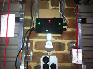
Installed
You'll note that the bulb poking out the bottom is close to the power point. If this were a standard incandescent bulb, it would be a fire waiting to happen. But this is a 5W LED (from eBay, of course) and perfect for casting enough light in the garage.

All Lit Up!
I also gave the front panel a coat of statin black paint - to hide the hot water label. The final code also flashes the front panel green LED at 1Hz (so you know it's running) and the red LED is on whenever an input is active.
Trials and Tribulations
The above glosses over a few mistakes and shortcomings I had to overcome.
Over-cooked Regulator
The first is what happens when re-purposing a design for a use it wasn't intended. The hot water controller used a TO92 7805 3 terminal regulator to provide 5V for the micro. The only load I added was the illumination of my push buttons, and as my dropping resistors were 470 ohms, each led was drawing around 10mA, or a lousy additional 30mA. That's not going to break anything, right?
Well, during coding, my 5V rail disappeared. The regulator died, and looking at some LM7805 datasheets on the web, the root cause was soon found. Although I'm used to using 7805's in a TO92 package that can deliver 100mA, others are flat out at only 50mA. So my three extra LEDs killed the regulator.
Over-stressed PIC
To get up and running again, I shoehorned in a TO220 7805, good for 1A, but I reversed the connections. I screwed up the input and output pins, and when turned on Vcc raised up to 7V, and the PIC18F2321 soon let out it's magic smoke.
Thankfully I had access to some PIC2480's which are pin compatible. So after switching out the dead 18F2321, and the regulator fitted the right way, I was back in action.
Unknown Input
During debugging, the my light input (red button) acted like it wasn't debouncing correctly. Now as I was using a common piece of code to debounce ALL inputs, it couldn't be a software problem.
One trick when developing firmware, is to make it obvious when your device resets. So for the first second after a reset I turn the front panel leds on, and wait. After adding this to my code, when I pressed the light button, rather than get a weird debounce behaviour, the front panel leds came on and thus the board had reset.
After having a quick look over the board, there appeared to be extra circuitry around this input. Rather than working out what this circuity did and why it didn't like being switched to ground, I simply moved this input from RA0 to RA4 (the two door controls beging RA1 and RA2), and the reset issue disappeared. Sorted.
Damn You Ultrabrite LEDS!
When installed, the illuminated buttons had one last surprise for me. The bloody things were so bright they were able to light up the garage enough to stop me bumping into things. So I did a brutal mod where I upped the dropping resistors from 470 ohms to 3k3 (the first 'biggish' value I found in my junk box). This is not the way to dim LEDS (Digikey have some better techniques here) and the brightness balance of all three LEDs was now screwed (one Green button is brighter than the other, the red button is dimmest of the three) but at least they are no longer 'stupidly bright'.
But still bright enough to be found in the dark :)
The Most Important Feedback
As I'm a massive geek, I have learnt that the family is not often as enthused about a project as I am. So I didn't explain what the new black box in the garage was for, and went to pick up my daughter from her drama class.
Pulling up in the garage, my daughter was impressed that we could now walk safely though the garage, and was impressed that the buttons *and* the remote controls could work the doors.
Yeah, that felt good.
"But you know what Dad?" she opined, "It would be cool if you could control it from your Mobile Phone."
eBay has the answer for that!
Nice read, thanks! The threaded retention system is a "Luer Lock" which is the medical industry standard for secure connections. Maybe a pharmacy would have insulin syringes for diabetics? Or maybe you could sweet talk your doctor into giving you a handful (I'd bring a copy of this post with pics so there's no worry of you being a junky)
ReplyDeleteFantastic!
DeleteAs a kid I used to make 'jumping beans' where you needed to buy empty capsules from the chemist. I'm used to getting weird looks from them.
You can buy the locking syringes off ebay
ReplyDeleteThat board was a real find! Too bad you couldn't get in the return center bin feed.
ReplyDeleteRe: button LED dimming; You've probably considered this already, but since you seem to have spare I/O on the PIC, why not use the PIC to provide PWM drive to a switch transistor and duty-cycle modulate the LEDS? This will dim them all the same amount.
You never finish a project, you just pick a place to stop :)
DeleteIf / when I get around to sticking the bluetooth module in, I'll take the PWM suggestion on board!
What a wonderful post—there’s something so exciting about finally finding the perfect lighting setup. It really does change everything, from mood to functionality. Lately, I’ve been learning more about advanced lighting solutions, and it reminded me of how Manmachine Automotive in India provides professional detailing lights that elevates spaces with precision and clarity. Your experience beautifully reflects how transformative good lighting can be!
ReplyDelete